
Finite Element Methods
Truck Chassis FEA Stress, Stiffness, and Modal Analysis and Design Modification
(MAJOR-Project MECE 4290U)
Finite Element Stress, Stiffness, and Optimization Study

Introduction
This project investigates the structural performance and optimization of a truck chassis using Finite Element Analysis (FEA). The study evaluates stress distribution, bending stiffness, torsional stiffness, and dynamic behavior (modal analysis) under representative loading and boundary conditions.
A structured mesh convergence and validation workflow was applied to ensure numerical reliability before proposing design modifications aimed at weight reduction. The final objective was to reduce chassis mass while preserving structural integrity and stiffness, demonstrating practical engineering judgment in simulation-driven design optimization.

Problem Definition & Engineering Objectives
The goal of this project was to analyze and optimize a steel truck chassis subjected to realistic service loads.
Key objectives included:
-
Evaluating global and local stress behavior
-
Quantifying bending and torsional stiffness
-
Identifying natural frequencies and mode shapes
-
Achieving a minimum target weight reduction without compromising performance
Material properties were based on ASTM A36 structural steel, and results were validated against simplified analytical calculations where applicable.


Geometry & Material Modeling
The provided 3D chassis CAD model was analyzed as a full structural assembly, excluding fasteners to reduce solver complexity.
Key modeling decisions:
-
Isotropic linear-elastic steel behavior
-
Structural members modeled with full geometric fidelity
-
Simplifications are justified to balance accuracy and computational efficiency
This ensured realistic stiffness representation while maintaining feasible simulation runtimes.
Boundary Conditions & Load Assumptions
Realistic boundary conditions were critical to this study. Engineering assumptions were made based on suspension mounting locations and project constraints:
-
Front suspension points modeled using added mounting nubs
-
Rear constraints applied at cross-beam interfaces
-
Static vertical load of 98,100 N distributed across the chassis deck
-
Center of gravity adjusted per project specifications
Separate boundary condition sets were implemented for:
-
Stress analysis
-
Bending stiffness
-
Torsional stiffness
-
Modal analysis (fixed-fixed and free-free)


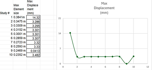
Mesh Strategy & Convergence Study
A systematic mesh sensitivity study was conducted across all analyses to ensure solution reliability.
Key features:
-
Up to 10 mesh refinement iterations
-
Monitoring of stress, displacement, and runtime
-
Combination of global mesh refinement and local mesh controls
-
Identification of convergence thresholds before result interpretation
This approach demonstrated best practices in finite element modeling and numerical verification.


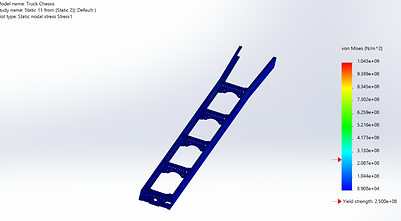
Stress Analysis Results
The static stress analysis identified:
-
Peak von Mises stresses at nub interfaces and cross-beam fillets
-
Maximum displacements at mid-span and end faces
-
Stable convergence after mesh refinement
Local mesh refinement improved stress resolution in high-gradient regions without unnecessary computational cost.


Bending Stiffness Evaluation
Bending stiffness was evaluated by applying vertical loads at the front suspension points.
Key outcomes:
-
Rapid stress convergence across mesh refinements
-
Initial displacement divergence corrected using local mesh controls
-
Final deflection patterns consistent with expected bending behavior
Results confirmed sufficient bending stiffness for the given material and geometry.


Torsional Stiffness Evaluation
Torsional loading was applied with opposing forces at the front suspension mounts.
Findings included:
-
Initial sensitivity to coarse mesh quality
-
Strong convergence after refinement
-
Torsional deformation concentrated near suspension interfaces
The chassis exhibited adequate torsional rigidity, with results suitable for comparative design assessment.


Modal Analysis & Dynamic Behavior
Modal analysis was conducted under both fixed-fixed and free-free conditions.
Key insights:
-
Fixed-fixed conditions produced artificially stiff frequency responses
-
Free-free conditions revealed physically meaningful mode shapes
-
First significant natural frequency observed near 13 Hz
This analysis provided insight into potential vibration sensitivity and structural resonance.


Design Modification & Weight Reduction Study
Design optimization focused on material removal from low-stress regions.
Implemented changes:
-
Slotting along C-beam lengths
-
Minor counterweight adjustments near high-deflection regions
Results:
-
Mass reduction achieved (below initial target)
-
Stress levels reduced
-
Some stiffness anomalies were observed due to solver limitations
This highlighted the trade-off between mass reduction and structural stiffness in practical design optimization.


Validation & Engineering Discussion
FEA results were compared against simplified analytical models.
Observations:
-
Large discrepancies (≈ 65–85%) due to modeling assumptions and solver behavior
-
Reinforced the importance of boundary condition realism
-
Demonstrated limitations of SolidWorks for high-fidelity structural optimization
The study emphasized engineering judgment over raw numerical results.
Conclusion
-
Successfully conducted multi-case structural FEA on a full vehicle chassis
-
Applied mesh convergence, local refinement, and result validation
-
Explored stress, stiffness, and dynamic behavior comprehensively
-
Demonstrated design optimization trade-offs
-
Identified areas where higher-end solvers (ANSYS) would improve fidelity
This project serves as a strong demonstration of applied finite element methods, simulation-driven design, and critical engineering evaluation.