Safe Design of a Stepped Shaft and its Analysis (MAJOR-Project for MECE 3220U)
FEA-backed design of a high-strength shaft ensuring structural safety and infinite fatigue life.

Introduction
This project focuses on designing a stepped shaft that can transmit loads safely while maintaining structural integrity and infinite fatigue life. Using stress analysis, material selection, and design optimization techniques, the team ensured that the final configuration meets a minimum factor of safety (FOS) of 1.5 for demanding applications, such as aerospace and automotive systems.
Stepped shafts are critical in mechanical systems due to their ability to handle torque, fit varying components, and distribute loads efficiently. The report examines the theoretical and practical design process for such a shaft under multiple real-world constraints, utilizing both analytical and computational methods.


Design Requirements & Assumptions
The shaft is designed under specific assumptions regarding load points, force directions, and material behavior. The group assumed press-fit attachments (no keyways) to reduce stress concentrations and focused on achieving the required safety margin without overdesigning. A 1.5+ FOS was targeted to meet both functional reliability and weight-efficiency, especially for aerospace applications.


Force Analysis
This section details internal forces like shear, bending moment, and torque using diagrams. These were used to locate critical stress zones and guide shaft geometry optimization. This analysis ensured that the shaft could handle torsional and bending stresses without risk of failure under complex loading.


Material Selection & Justification
Several materials were evaluated, including AISI 4340 and 4140, but AISI 1045 Cold Drawn (CD) steel was chosen for its balance of strength, fatigue resistance, and availability of reliable design data. The material selection aligns with cost, performance, and manufacturability goals.


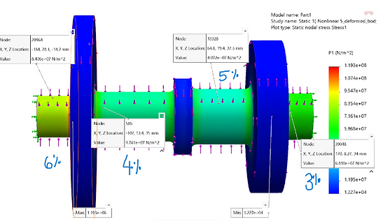
Finite Element Analysis (FEA) Validation
The stepped shaft was modeled in SolidWorks, and FEA was conducted using realistic loading and boundary conditions. Due to computational limits, a moderate mesh density was used. Stress and displacement plots validated the design’s strength and helped visualize high-stress zones.


Finite Element Analysis (FEA) Validation
Iterations were conducted on shaft diameters and fillet radii to optimize weight, cost, and performance. Final shaft dimensions (e.g., 63 mm for Shaft 1) were chosen to meet or exceed safety factors, reduce stress concentrations, and ensure manufacturability without overengineering.

Conclusion
FEA results showed maximum stress concentration on Shaft 3, with a calculated theoretical safety factor of ~5.8 and a 5.8% error from manual calculations—an acceptable margin. Manufacturing quality control methods like CMM, MPI, and Rockwell hardness testing were suggested for post-fabrication validation.
AISI 1045 CD and optimized shaft dimensions achieved the design goal of a safe, reliable, and fatigue-resistant stepped shaft. Final safety factors averaged 2.0, and the model proved feasible for both aerospace and automotive use. Future steps include testing other materials (like AISI 4340) and integrating the keyway/retaining ring design.