

Yash's Personal Projects
Dual-Blade Rotary Gear Design

Project Overview
This project explores a dual-blade rotary gear system inspired by the mechanics of a tiltrotor aircraft. The goal was to design and simulate a synchronized dual-rotor mechanism that mimics real-world tiltrotor behavior using gear-driven motion. The design was developed with future applications in VTOL drones, robotic systems, and aerospace-inspired mechanical prototypes.

Design & Development
-
Created a dual-rotor system using custom gear arrangements to achieve synchronized, opposing motion.
-
Modeled in SolidWorks, with attention to gear meshing, link length optimization, and rotational symmetry.
-
Integrated motion studies to visualize phase timing, angular velocity, and smooth gear operation
-
Produced engineering drawings and an exploded view to communicate part relationships and assembly
Project Highlights
-
Simulated realistic rotor synchronization with 3 DOF
-
Designed a modular and scalable mechanism that could be adapted for drones, robots, or mechanical walkers
-
Strengthened skills in mechanism design, CAD animation, and aerospace-inspired kinematics
Project Takeaways
This project helped bridge the gap between aerospace inspiration and mechanical design implementation. It demonstrated how complex real-world motion (like the tiltrotor system) can be scaled down and modeled using accessible CAD tools to explore innovation in robotic motion and advanced gearing.
Future Enhancements
-
Run FEA (Finite Element Analysis) on gear teeth and rotor hubs
-
Add motor mount points for functional prototyping
-
Integrate electronic control systems for tilt/rotation coordination
-
Explore biomimetic applications in legged robots or adaptive systems
Airfoils CFD Analysis of NACA Profiles Using SolidWorks Flow Simulation

Project Overview
This project explored the aerodynamic behavior of various NACA airfoil profiles under different angles of attack using SolidWorks Flow Simulation. The goal was to evaluate lift, drag, and stall characteristics to deepen understanding of airfoil performance and fluid dynamics.
To simulate and analyze multiple NACA airfoils using CFD techniques and extract meaningful aerodynamic performance data (Cl, Cd) to assess their efficiency and stall behavior.

Process & Tools Used
Software:
-
SolidWorks Flow Simulation
-
Airfoil Modeling: Designed NACA profiles with variable geometries and attack angles.
-
Simulation Setup: Applied appropriate boundary conditions, flow speed, and turbulence models.
-
Analysis Tools:
-
Streamline visualization
-
Pressure distribution plots
-
Lift (Cl) and drag (Cd) coefficient extraction
-
-
Post-Processing: Generated Cl/Cd vs. AoA plots to compare efficiency and stall onset.


Results & Reflections
-
Successfully simulated aerodynamic flow across multiple airfoils.
-
Identified stall angles and efficiency trends among profiles.
-
Visualized flow separation, pressure gradients, and wake formation.
-
Strengthened skills in CFD, parametric studies, and aerodynamic analysis.
-
Built foundational knowledge useful for applications in aviation, wind energy, and UAV design.
Skills Gained:
-
CFD Simulation & Setup (SolidWorks Flow)
-
Understanding of Lift/Drag Theory
-
Parametric & Comparative Analysis
-
Data Visualization & Engineering Interpretation
-
Applied Fluid Mechanics


Thermodynamic Cycle Calculator & Simulator with Automated Report Generator

Project Overview
This project involved developing a thermodynamic cycle simulator and calculator capable of computing and visualizing key parameters, including thermal efficiency, work done, heat transfer, and pressure-volume (PV) diagrams. The tool was developed to simulate ideal cycles like the Otto, Diesel, and Rankine cycles.


Key
Features
-
Cycle Calculations: Simulated performance metrics based on user-defined initial conditions (pressure, temperature, volume, compression ratio, etc.)
-
Formulas Integrated: Included equations from the first law of thermodynamics and isentropic relations.
-
Graph Plotting: PV and TS diagrams generated dynamically using MATLAB and Matplotlib.
-
Automated Report Generator: Outputs a professionally formatted PDF report summarizing input values, assumptions, cycle parameters, and plots.
Challenges Solved
-
Built a dynamic user input handler to limit errors.
-
Used data validation techniques to avoid unphysical results.
-
Optimized equation solvers for faster report generation.
What I Learned
-
Applied real-world thermodynamic concepts from textbooks to programmable tools.
-
Developed a strong understanding of simulation workflows, data visualization, and report automation.
-
Strengthened logical thinking and algorithm design with Python and MATLAB.
DEMO
Workcell Design for Efficient CNC-to-CMM Workflow with Automated Handling

Project Overview
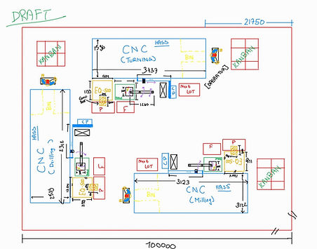
This project focused on designing a high-efficiency manufacturing workcell to streamline the transfer of precision-machined parts from a CNC machining center to a Coordinate Measuring Machine (CMM) for inspection. By integrating automated part handling and optimizing the physical layout, the goal was to reduce transfer time, minimize manual intervention, and enhance throughput in a production environment.
Objective

-
Develop a CAD-based workcell layout that enables seamless CNC-to-CMM workflow.
-
Incorporate robotics or automated handling systems to reduce operator dependency.
-
Optimize space utilization and ergonomics while ensuring collision-free operations.
-
Improve inspection feedback time to accelerate production decision-making.
Methodology
-
Requirements Analysis
-
Gathered machine specifications, floor space constraints, and operator workflow data.
-
Identified key pain points in the current CNC-to-CMM transfer process, including delays and manual handling inefficiencies.
-
CAD Modeling in SolidWorks
-
Created accurate 3D models of the CNC machine, CMM, worktables, and handling equipment.
-
Simulated part placement, machine access points, and operator reach zones.
-
Automation Integration
-
Designed provisions for robotic arm integration, palletizing systems, or automated guided carts (AGCs).
-
Included safety barriers and light curtain zones in the layout.
-
Ergonomic & Lean Optimization
-
Applied lean manufacturing principles to minimize unnecessary motion and reduce cycle time.
-
Used ergonomic reach envelopes to ensure safe manual interaction where necessary.
.jpg)
Impact
This design supports higher manufacturing throughput, improved quality control, and enhanced worker safety. By providing an efficient and automation-ready workflow, the solution positions the production line for scalability and Industry 4.0 integration.